Water Cooler Schematic Diagram

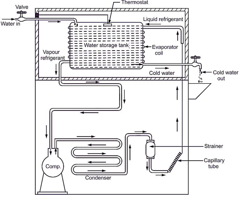
Water Cooler Schematic Diagram A water cooler schematic diagram reveals the inner workings of a typical water cooler. it is a useful tool for understanding how the components of the system interact and work together. a water cooler is an essential device in many homes and businesses, providing a convenient source of cold water. but, do you ever wonder what goes on inside its. Water cooler has a metal sheet cabinet. it consists of a hermetically sealed compressor, condenser, capillary tube, accumulator, refrigerant coil, water cooling coil, thermostat, relay, overload protection etc. thermostat is provided to control the temperature of water. separate inlet and outlet connections of water are provided to storage tank.

What Is Water Cooler Working Diagram Types Electricalworkbook This article will explore the benefits of a water cooler diagram, as well as some tips for wiring one. understanding how water cooler diagrams work. a water cooler diagram is essentially a blueprint that shows the layout and components of a water cooler system. it helps you visualize and understand how all the pieces fit together. This video discusses the wiring diagram & electrical symbols for a mini refrigerator & water cooler. the instructor will show the students how to build a leg. Understanding the water cooler schematic diagram can help you troubleshoot problems, make repairs, and even install a new one. at the heart of the water cooler is a refrigeration system that uses an electric fan forced air compressor, a condensing evaporator coil, and a cooling fan. this system is responsible for cooling the water inside the tank. Page 4 enlzs8ws 1g secure cooler frame to wall by installing (2) screws and washers (not supplied). fig. 2 fig. 3 lay gasket along back of bottle filler mounting plate. align bf and lay on cooler basin. fig. 4 attach the 3 8 water line into the bulkhead fitting. (gasket removed from bottle filler for clarity) fig.

Comments are closed.