Ppt Chapter 7 Complementary Mos Cmos Logic Design Powerpoint

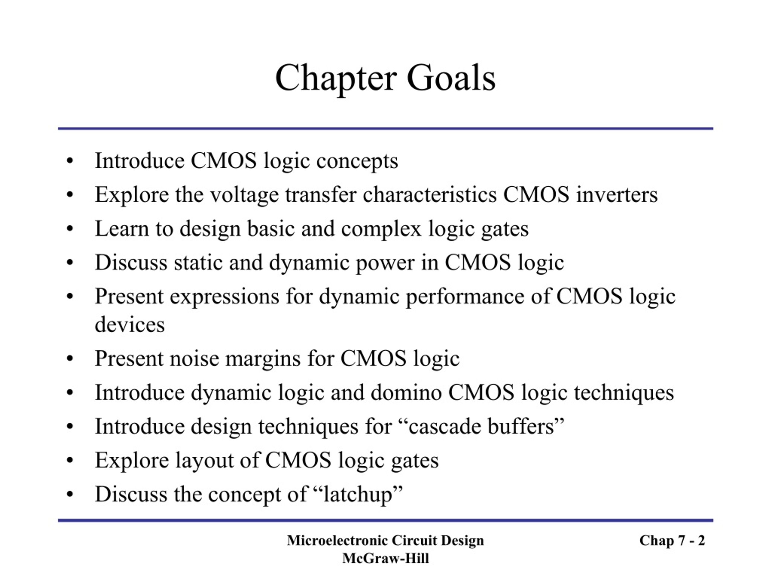
Ppt Chapter 7 Complementary Mos Cmos Logic Design Powerpoint Chapter 7 complementary mos (cmos) logic design. microelectronic circuit design richard c. jaeger travis n. blalock. chapter goals. introduce cmos logic concepts explore the voltage transfer characteristics cmos inverters learn to design basic and complex logic gates slideshow 5599245 by marcel. Complex cmos gate with a bridging transistor design example • design a cmos gate that implements the following logic function using the same reference inverter sizes as the previous example: y = ab ce ade cdb • the nmos branch can be realized in the following manner using bridging nmos d to implement y.

Ppt Chapter 7 Complementary Mos Cmos Logic Design Powerpoint 35 complex cmos logic gate design example by placing nodes in the interior of each arc, plus two more outside the graph for vdd (3) and the complementary output (2’), the pmos branch can be realized as shown on the left figure connect all of the nodes in the manner shown in the right figure, and the nmos arc that pmos arc intersects have the same inputs microelectronic circuit design mcgraw hill. Chap7 complementary mos (cmos) logic design free download as powerpoint presentation (.ppt), pdf file (.pdf), text file (.txt) or view presentation slides online. this chapter discusses cmos logic design. it introduces cmos inverters and their voltage transfer characteristics. the chapter explores how to design basic and complex logic gates. To draw the graph for the complementary pmos logic: place nodes in the interior of each enclosed path: (4) and (5) place two more outside the graph for vdd (3) and the complementary output (2’) connect all of the nodes by drawing the arcs (pmos transistors) that cut the arcs of the. original nmos graph. G. gargikhanna1. nmos, pmos, and cmos logic gates are implemented using mosfet transistors. nmos logic uses n type mosfets that have high resistance with low voltage and low resistance with high voltage. pmos logic uses p type mosfets that have the opposite behavior. cmos logic uses both n type and p type mosfets together to realize gates.

Ppt Chapter 7 Complementary Mos Cmos Logic Design Powerpoint To draw the graph for the complementary pmos logic: place nodes in the interior of each enclosed path: (4) and (5) place two more outside the graph for vdd (3) and the complementary output (2’) connect all of the nodes by drawing the arcs (pmos transistors) that cut the arcs of the. original nmos graph. G. gargikhanna1. nmos, pmos, and cmos logic gates are implemented using mosfet transistors. nmos logic uses n type mosfets that have high resistance with low voltage and low resistance with high voltage. pmos logic uses p type mosfets that have the opposite behavior. cmos logic uses both n type and p type mosfets together to realize gates. 18. clocked cmos (c2mos) (c2mos) is a logic family that combines static logic design with the synchronization achieved by using clock signals. the inputs a, b, and c are connected to complementary nfet pfet pairs as in ordinary static design where they act like open or closed switches. when the clock is at a level of ϕ=1 both mn and mp are. Microelectronic circuit design, 4e mcgraw hill chap 7 * chapter 7 complementary mos (cmos) logic design microelectronic circuit design richard c. jaeger travis n. blalock….

Ppt Chapter 7 Complementary Mos Cmos Logic Design Powerpoint 18. clocked cmos (c2mos) (c2mos) is a logic family that combines static logic design with the synchronization achieved by using clock signals. the inputs a, b, and c are connected to complementary nfet pfet pairs as in ordinary static design where they act like open or closed switches. when the clock is at a level of ϕ=1 both mn and mp are. Microelectronic circuit design, 4e mcgraw hill chap 7 * chapter 7 complementary mos (cmos) logic design microelectronic circuit design richard c. jaeger travis n. blalock….

Ppt Chapter 7 Complementary Mos Cmos Logic Design D

Comments are closed.