Plc Control Panel Wiring Diagram Pdf

Plc Panel Wiring Diagram Pdf Electrical wiring diagrams of a plc panel. in an industrial setting a plc is not simply “plugged into a wall socket”. the electrical design for each machine must include at least the following components. a control system of a plc panel will normally use ac and dc power at different voltage levels. After the cpu processes the input data (input scan), it will then make any needed output changes after executing the user program (output scan). there are four basic steps in the operation of all plcs: input scan, program scan, output scan, and housekeeping. these steps continually take place in a repeating loop.

Plc Control Panel Wiring Diagram Pdf These numbers are the screw numbers on the front connector of the card. same as our plc, we have to connect a 24 volt power to turn on our plc card. if you compare it with the card’s wiring diagram within its manual, then you see that the connection number 1 and 20 are for connecting the 24 volt dc power. Required when a two wire control device is used. the bulletin 595 auxiliary contacts are designed as “a” and “b” on the wiring diagram. these contacts are easily. added to any allen bradley bulletin 500 starter sizes 0 through 4. when this system is used, the phase connections on all of the starters must be the same. In conclusion, plc control panel wiring is the process of connecting various electrical components in a control panel to a programmable logic controller. it involves organizing and labeling wires, following schematic diagrams, and adhering to industry standards. proper wiring is essential for the functionality and safety of the automated system. Qualified personnel the product system described in this documentation may be operated only by personnel qualified for the specific task in accordance with the relevant documentation, in particular its warning notices and safety instructions.

How To Wire A Plc Control Panel In conclusion, plc control panel wiring is the process of connecting various electrical components in a control panel to a programmable logic controller. it involves organizing and labeling wires, following schematic diagrams, and adhering to industry standards. proper wiring is essential for the functionality and safety of the automated system. Qualified personnel the product system described in this documentation may be operated only by personnel qualified for the specific task in accordance with the relevant documentation, in particular its warning notices and safety instructions. Digital inputs. firstly, take digital inputs. according to sink or source wiring, connect either 24v or 0v to the plc common. so, for example, if the common is 24v, connect 0v to all the respective plc field inputs in the terminal board. as one board has two pins, one will be used to provide 0v and the other will be connected to plc digital input. A plc (programmable logic controller) is an essential component in industrial automation systems. it is used to control and monitor various processes and machines in a factory or industrial setting. a plc wiring diagram is a graphical representation of the electrical connections, input and output devices, and control modules within a plc system.

How To Wire A Plc Control Panel Digital inputs. firstly, take digital inputs. according to sink or source wiring, connect either 24v or 0v to the plc common. so, for example, if the common is 24v, connect 0v to all the respective plc field inputs in the terminal board. as one board has two pins, one will be used to provide 0v and the other will be connected to plc digital input. A plc (programmable logic controller) is an essential component in industrial automation systems. it is used to control and monitor various processes and machines in a factory or industrial setting. a plc wiring diagram is a graphical representation of the electrical connections, input and output devices, and control modules within a plc system.

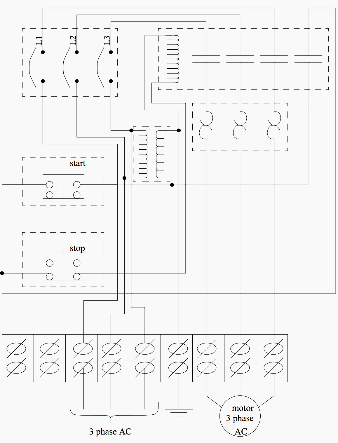
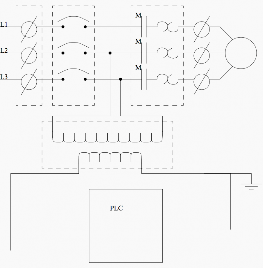
Basic Electrical Design Of A Plc Panel Wiring Diagrams Eep

Comments are closed.