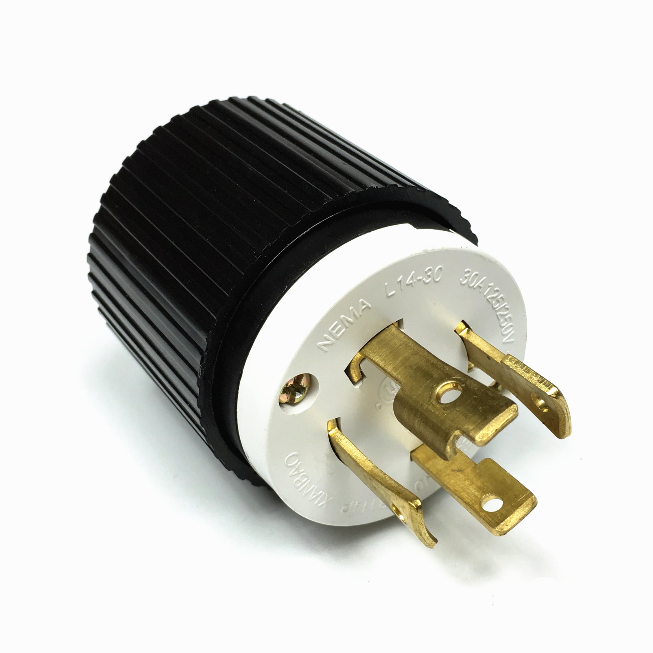
Pin On L14

How To Wire A L14 30p Plug Make sure that the voltage matches the expected rating (usually 240 volts for a nema l14 30p). if the voltage is significantly lower or higher, there may be a problem with the power supply or wiring. 3. check the circuit breaker: verify that the circuit breaker for the nema l14 30p receptacle is in the “on” position. Overall, how satisfied are you with the lenovo support website today? document id:um924765. original publish date:12 14 2020. last modified date:08 29 2023. stay in touch.

L14 Electrical Wiring Diagrams The first step in wiring a nema l14 20 outlet is to turn off the power supply to the circuit. this can be done by switching off the circuit breaker or removing the fuse. it is crucial to cut off the power to avoid any accidents or electrical shock during the installation process. Description. nema l14 30 30a, 125 250v ac, 3p 4w. design features for plug & connector. •all nylon construction. •epdm gasket seals cord hole from dust and debris. •back wire terminal clamps for easy secure wiring. •individual wiring compartments with tapered channel for easy insertion of wires. •clear cover over wiring compartments. The procedure for wiring a nema l14 30 receptacle is similar to the one for wiring a plug. the 10 gauge, 3 conductor cable must be connected to a 240 volt, 30 amp breaker in the main panel. receptacles are stationary and designed to handle 10 gauge wire, so you usually don't need to crimp connection rings onto the wires. Cut the wires: using a pair of wire cutters or scissors, carefully cut the wires to the desired length. make sure to leave enough excess wire to comfortably reach the nema l14 30 plug without any tension or strain. 4. strip the wires: with the wire strippers, remove approximately 1 inch of insulation from the end of each wire.

Nema L14 20p To 420c12w Pin And Sleeve Connector Locking Power Cords The procedure for wiring a nema l14 30 receptacle is similar to the one for wiring a plug. the 10 gauge, 3 conductor cable must be connected to a 240 volt, 30 amp breaker in the main panel. receptacles are stationary and designed to handle 10 gauge wire, so you usually don't need to crimp connection rings onto the wires. Cut the wires: using a pair of wire cutters or scissors, carefully cut the wires to the desired length. make sure to leave enough excess wire to comfortably reach the nema l14 30 plug without any tension or strain. 4. strip the wires: with the wire strippers, remove approximately 1 inch of insulation from the end of each wire. 5. connect the ac power adapter and all disconnected cables to the computer. usb and audio board (for l14 gen 2 only) prerequisite before you start, read generic safety and compliance notices and print the following instructions. attention: do not touch the contact edge of the memory module. Wiring l14 30 plug. to properly wire a nema l14 30 device, you'll need 4 conductors. proper wiring. in your situation, i'd pull an extra red or black conductor from the panel to the receptacle location and remove either the green or bare conductor. then you'll connect the original black conductor from the breaker, to x on the receptacle.

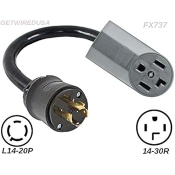
L14 20p Male 4 Pin Plug To L14 30r 4 Prong Female Receptacle Outlet 5. connect the ac power adapter and all disconnected cables to the computer. usb and audio board (for l14 gen 2 only) prerequisite before you start, read generic safety and compliance notices and print the following instructions. attention: do not touch the contact edge of the memory module. Wiring l14 30 plug. to properly wire a nema l14 30 device, you'll need 4 conductors. proper wiring. in your situation, i'd pull an extra red or black conductor from the panel to the receptacle location and remove either the green or bare conductor. then you'll connect the original black conductor from the breaker, to x on the receptacle.

Comments are closed.