Logic Diagram Of Nand Gate

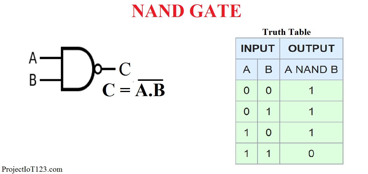
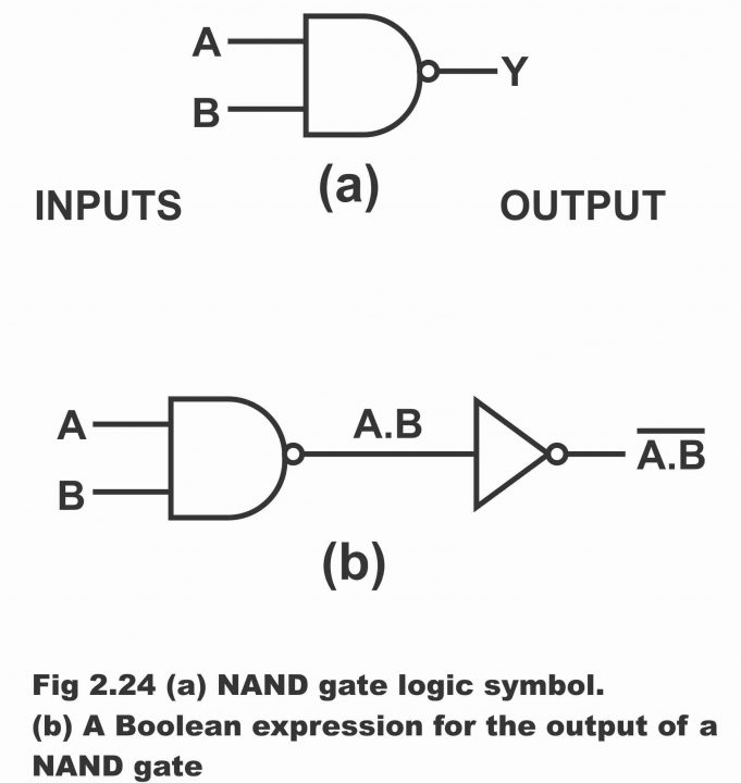
Nand Gate Logic Diagram Learn how to construct and use a logic nand gate, a combination of an and gate and a not gate. see the symbol, truth table, boolean expression and universal property of the nand gate. A nand gate (“not and gate”) is a logic gate that produces a low output (0) only if all its inputs are true, and high output (1) otherwise. hence the nand gate is the inverse of an and gate, and its circuit is produced by connecting an and gate to a not gate. just like an and gate, a nand gate may have any number of input probes but only.

Logic Nand Gate Working Principle Circuit Diagram Nand gate takes boolean values as input and returns: returns 1, if all the inputs are 0 or alternative (meaning one is 0, and the other is 1 or vice versa). the boolean expression of nand gate is as follows –. say we have two inputs, a and b and the output is called x, then the expression is –. x = (a . b)’. A nand gate is a logic gate where the output goes low (or “0”) only if all its inputs are high (or “1”). the schematic symbol for a nand gate is like the and gate, just with a circle at the output to indicate that it’s an inverted version of and. “nand” stands for not and because it’s the same as an and gate with a not gate on. Diagram of the nand gates in a cmos type 4011 integrated circuit. nand gates are basic logic gates, and as such they are recognised in ttl and cmos ics. the standard, 4000 series, cmos ic is the 4011, which includes four independent, two input, nand gates. these devices are available from many semiconductor manufacturers. A nand gate, short for “not and” gate, is a type of logic gate that produces an output signal only when all of its input signals are not true. it is essentially an and gate followed by a not gate. the symbol for a nand gate consists of two inputs, denoted by lines entering the gate, and a single output, represented by a line exiting the gate.

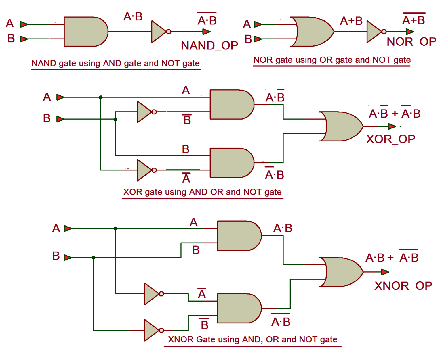
Logic Diagram Of Nand Gate Diagram of the nand gates in a cmos type 4011 integrated circuit. nand gates are basic logic gates, and as such they are recognised in ttl and cmos ics. the standard, 4000 series, cmos ic is the 4011, which includes four independent, two input, nand gates. these devices are available from many semiconductor manufacturers. A nand gate, short for “not and” gate, is a type of logic gate that produces an output signal only when all of its input signals are not true. it is essentially an and gate followed by a not gate. the symbol for a nand gate consists of two inputs, denoted by lines entering the gate, and a single output, represented by a line exiting the gate. Nand gate with 3 inputs – truth table & circuit diagram. the nand gate is the most important logic gate in digital electronics. it is one of the universal logic gates. because other logical gates can be designed by using nand gates only. this gate is available in ic form. ic7400 is a popular ic that consists of 4 nand gates. Learn about the logic nand gate, a universal logic gate that can implement any basic logic function. see its symbol, truth table, boolean expression, electrical equivalent circuit, and how to realize other logic gates using nand gate.

Comments are closed.