Ladder Diagrams

What Is Ladder Diagram Edrawmax Online Learn how to draw and interpret ladder diagrams, a type of schematic for industrial control logic systems. find out the rules and conventions for wire numbers, rails, rungs, and load devices in ladder diagrams. Learn how to program a plc using ladder logic, a graphical language that resembles relay circuits. find out the seven basic parts of a ladder diagram, the binary and logic concepts, and the fundamental logic functions.

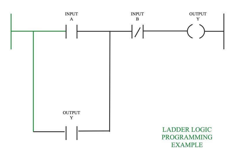
Ladder Diagram Examples Ladder logic (also known as ladder diagram or ld) is a programming language used to program a plc (programmable logic controller). it is a graphical plc programming language which expresses logic operations with symbolic notation. ladder logic is made out of rungs of logic, forming what looks like a ladder – hence the name ‘ladder logic’. A ladder diagram is a type of schematic diagram used in industrial automation, describing circuits for logic control. two vertical control rails and horizontal logic rungs make up the ladder diagrams to form what appears like a ladder. Learn the basics of ladder logic, a popular plc programming language that mimics electrical circuits. see examples of ladder diagrams, circuit branches, and how to troubleshoot common problems. Ladder logic. ladder logic was originally a written method to document the design and construction of relay racks as used in manufacturing and process control. [1] each device in the relay rack would be represented by a symbol on the ladder diagram with connections between those devices shown. in addition, other items external to the relay rack.

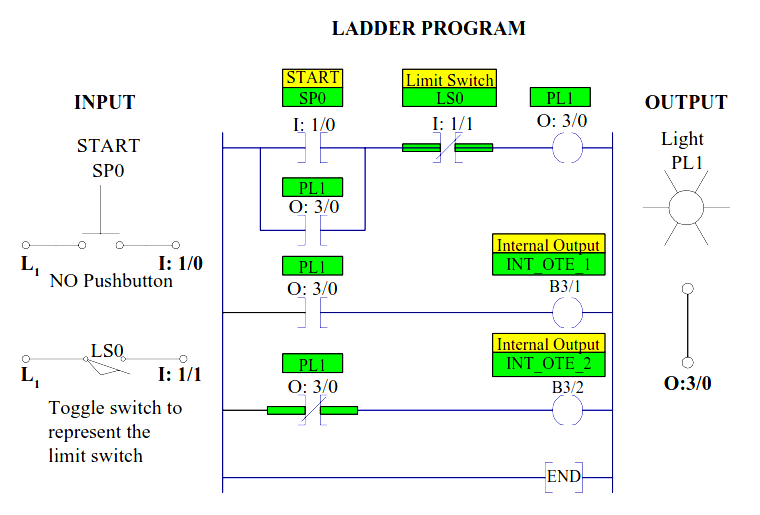
Ladder Diagrams Automation Community Learn the basics of ladder logic, a popular plc programming language that mimics electrical circuits. see examples of ladder diagrams, circuit branches, and how to troubleshoot common problems. Ladder logic. ladder logic was originally a written method to document the design and construction of relay racks as used in manufacturing and process control. [1] each device in the relay rack would be represented by a symbol on the ladder diagram with connections between those devices shown. in addition, other items external to the relay rack. Ladder logic was designed to have the same look and feel as electrical ladder diagrams, but with ladder logic, the physical contacts and coils are replaced with memory bits. let’s take a look. for this program, the relay logic’s ladder diagram is duplicated with ladder logic; no more hard wired logic, but memory locations instead. Think of ladder logic symbols as the essential pieces of a puzzle in ladder diagrams. this guide covers all these crucial symbols, as defined in iec 61131 3, and offers them for download in various formats, including a handy pdf. understanding ladder logic symbols is key—they each stand for a specific instruction, like a secret code.

Plc Ladder Logic Diagram Examples Wiring Diagram And Schematics Ladder logic was designed to have the same look and feel as electrical ladder diagrams, but with ladder logic, the physical contacts and coils are replaced with memory bits. let’s take a look. for this program, the relay logic’s ladder diagram is duplicated with ladder logic; no more hard wired logic, but memory locations instead. Think of ladder logic symbols as the essential pieces of a puzzle in ladder diagrams. this guide covers all these crucial symbols, as defined in iec 61131 3, and offers them for download in various formats, including a handy pdf. understanding ladder logic symbols is key—they each stand for a specific instruction, like a secret code.

Comments are closed.