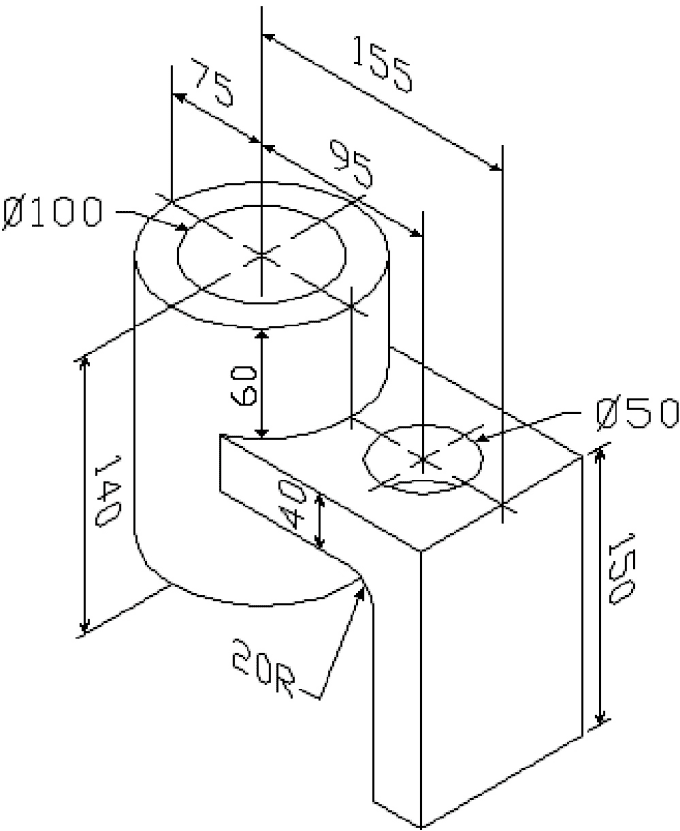
Image Result For Detailed Assembly Drawing Isometric Drawing Autocad

Image Result For Detailed Assembly Drawing Autocad Isometricо In simple terms, isometric drawings are three dimensional representations of an object, which are drawn on a two dimensional plane. this technique is used in drafting and design to show an object’s features more clearly with a realistic view. isometric drawings can be created in autocad with ease and accuracy with the help of some essential. How to turn on isodraft mode in autocad. there are a couple of ways to turn on isodraft to allow for isometric drawings. the first is typical of autocad—type it into the command line! when you do, you’ll see four options appear (or if you have dynamic input turned on, they’ll appear in the menu near your cursor).

Isometric Drawing For Beginners Pdf Bmp I Learn autocad for free using this step by step autocad tutorial series containing nearly 40 videos with lesson files sourcecad courses autocad es. Usd 3d image result for detailed assembly drawing autocad isometric drawing models for download, files in usd with low poly, animated, rigged, game, and vr options. New field welds can be added to the iso if you specify the "place field welds at maximum pipe length" setting. if you have selected "iso drawing" the spool section is used to define spools to be annotated within that iso, and consequently the isos will split sheets at spool boundaries, but can contain multiple spools. Learn how to use commands for creating and modifying 2d isometric drawings in autocad. find out how to switch between isometric and rectangular grids, use object snaps and tracking, and more.

How To Draw Isometric Drawing In Autocad Easily Draw Isometric C New field welds can be added to the iso if you specify the "place field welds at maximum pipe length" setting. if you have selected "iso drawing" the spool section is used to define spools to be annotated within that iso, and consequently the isos will split sheets at spool boundaries, but can contain multiple spools. Learn how to use commands for creating and modifying 2d isometric drawings in autocad. find out how to switch between isometric and rectangular grids, use object snaps and tracking, and more. In this video, we'll take you through a step by step guide on how to create stunning 3d isometric drawings in autocad. you'll learn advanced tips and tricks. Isometric drawing vs. isometric projection: the difference. the term isometric drawing is sometimes used synonymously with the term isometric projection. however, while both the isometric drawing and isometric projection represent 3d objects, which may perhaps be the source of the confusion, we want to point out that there is a significant difference between the two terms.

Comments are closed.