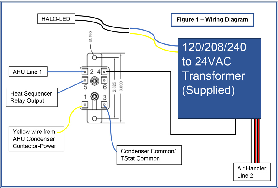
Fan Relay Wiring Diagram Hvac Wiring Diagram

Fan Relay Wiring Diagram Hvac Wiring Diagram Again, ensure a secure connection to prevent any loose wires. if you are using a fan center relay, you will need to connect the high voltage wires as well. locate the terminals labeled “line” and “load” on the relay strip. connect the incoming power wires to the “line” terminals, typically labeled as “l1” and “l2.”. Step 3: connect the wires to the relay terminals. connect the wire from the control signal (thermostat or control board) to the coil terminal of the relay. this wire will send the control signal to the relay when a temperature change is detected, activating or deactivating the hvac system.

Hvac Fan Relay Wiring Diagram Wiring Diagram And Schematic Hvac wiring diagram and legend. we’ll jump right into showing you a schematic diagram for a simple air conditioning unit. we’ll make a ladder diagram using a simple air conditioner as our example. first we have the main electrical supply lines l1 and l2 providing 208 230 volt, single phase power. then we’ll need a transformer to provide. About press copyright contact us creators advertise developers terms privacy policy & safety how works test new features nfl sunday ticket press copyright. An air conditioner relay wiring diagram is a visual representation of the electrical connections and components in an air conditioning system that are controlled by relays. relays are electromechanical switches that allow a low power signal to control a high power circuit. in the case of an air conditioner, relays are used to control the. In the case of the 90 340, it is the bottom two terminals of the relay. even though the coil is unmarked on most 90 340 relays, you can find it easily by locating the terminals with the small strands of wire connected. these two points connect through the electromagnetic coil. when 24 volts of potential is applied across the coil, the switch.
Understanding The Hvac Fan Relay Wiring Diagram Moo Wiring An air conditioner relay wiring diagram is a visual representation of the electrical connections and components in an air conditioning system that are controlled by relays. relays are electromechanical switches that allow a low power signal to control a high power circuit. in the case of an air conditioner, relays are used to control the. In the case of the 90 340, it is the bottom two terminals of the relay. even though the coil is unmarked on most 90 340 relays, you can find it easily by locating the terminals with the small strands of wire connected. these two points connect through the electromagnetic coil. when 24 volts of potential is applied across the coil, the switch. Step 4: connect the power supply. start by connecting the power supply wires to the air handler. this typically involves connecting the black wire to the live (hot) terminal, the white wire to the neutral terminal, and the green or bare copper wire to the ground terminal. step 5: wire the thermostat. The control wiring diagram includes: power supply connections: the diagram shows how the system is connected to the electrical power source, including the main voltage and ground connections. control devices: it illustrates the various control devices used in the hvac system, such as thermostats, pressure switches, relays, and contactors.

Comments are closed.