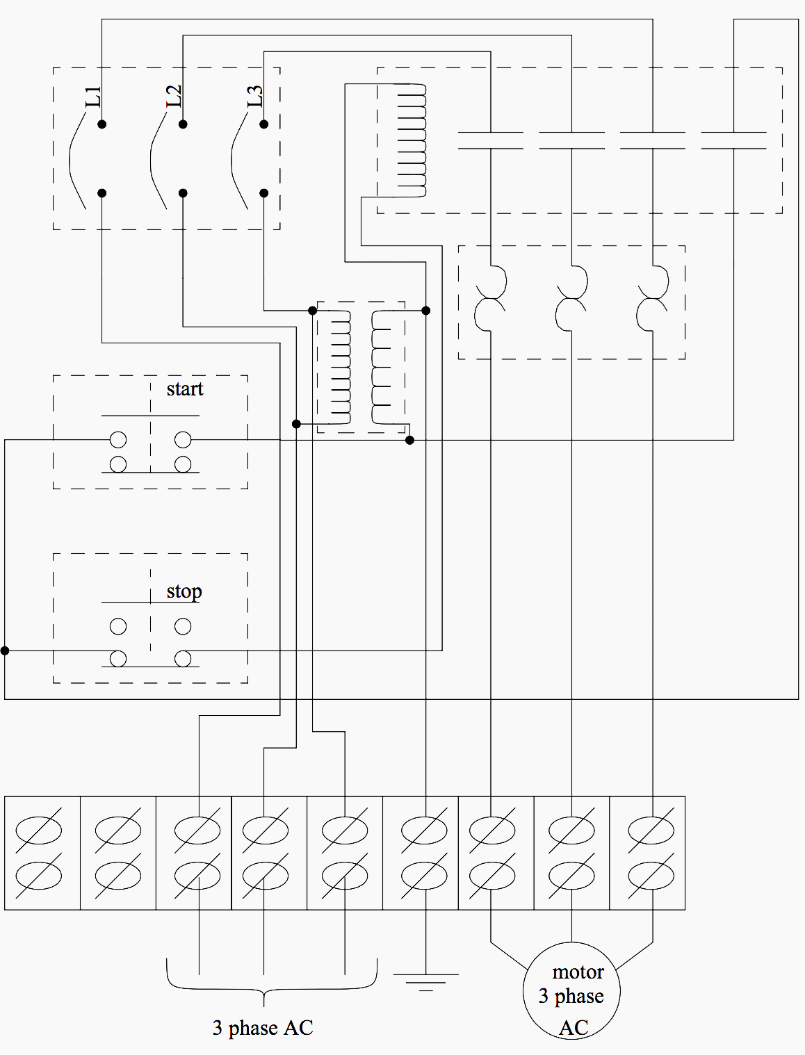
Control Panel Wiring Diagrams

How To Wire A Plc Control Panel Electrical wiring diagrams of a plc panel. in an industrial setting a plc is not simply “plugged into a wall socket”. the electrical design for each machine must include at least the following components. a control system of a plc panel will normally use ac and dc power at different voltage levels. Electrical panel wiring diagrams are used to outline each device, as well as the connection between the devices found within an electrical panel. as electrical panels are what will contain control systems, panel wiring diagrams are commonly encountered by plc technicians and engineers. although electrical panels may not be overly complex from the first glance, a lot of engineering goes into.

Control Panel Wiring Diagram A panel wiring diagram is a visual representation of the electrical connections and components within a control panel. it shows how various devices, such as switches, relays, and terminals, are wired together to create a functioning electrical system. this diagram is essential for electricians, technicians, and engineers who work with control. The idea of the electrical or wiring diagram is to trace the flow of power and signals between the sources, control devices, and final loads. these will usually be drawn in a line format from left to right, but are not analogous to ladder diagrams. reading electrical diagrams is one of the most important skills for anyone in a troubleshooting. Wiring diagram. now you maybe be curious how you should know which input on the plc you should connect the emergency stop to. well, this is simply done based on the wiring diagram. in a later article, we will get into the details of the wiring diagram and show you how simple it is to read and carry out the control panel wiring. . These numbers are the screw numbers on the front connector of the card. same as our plc, we have to connect a 24 volt power to turn on our plc card. if you compare it with the card’s wiring diagram within its manual, then you see that the connection number 1 and 20 are for connecting the 24 volt dc power.

Basic Electrical Design Of A Plc Panel Wiring Diagrams Eep Wiring diagram. now you maybe be curious how you should know which input on the plc you should connect the emergency stop to. well, this is simply done based on the wiring diagram. in a later article, we will get into the details of the wiring diagram and show you how simple it is to read and carry out the control panel wiring. . These numbers are the screw numbers on the front connector of the card. same as our plc, we have to connect a 24 volt power to turn on our plc card. if you compare it with the card’s wiring diagram within its manual, then you see that the connection number 1 and 20 are for connecting the 24 volt dc power. In conclusion, plc control panel wiring is the process of connecting various electrical components in a control panel to a programmable logic controller. it involves organizing and labeling wires, following schematic diagrams, and adhering to industry standards. proper wiring is essential for the functionality and safety of the automated system. – each page of the wiring diagram shows the exact wiring for different sections of the control panel. – each of the wires in the wiring diagram has a tag number. these tags can be found in the panel as well. – using the page numbers and the sections, in the wiring diagram, you can easily follow the wires and see where each wire is coming.

Electrical Control Panel Wiring Diagram Pdf In conclusion, plc control panel wiring is the process of connecting various electrical components in a control panel to a programmable logic controller. it involves organizing and labeling wires, following schematic diagrams, and adhering to industry standards. proper wiring is essential for the functionality and safety of the automated system. – each page of the wiring diagram shows the exact wiring for different sections of the control panel. – each of the wires in the wiring diagram has a tag number. these tags can be found in the panel as well. – using the page numbers and the sections, in the wiring diagram, you can easily follow the wires and see where each wire is coming.

Comments are closed.