Cmos Nand Gate Truth Table

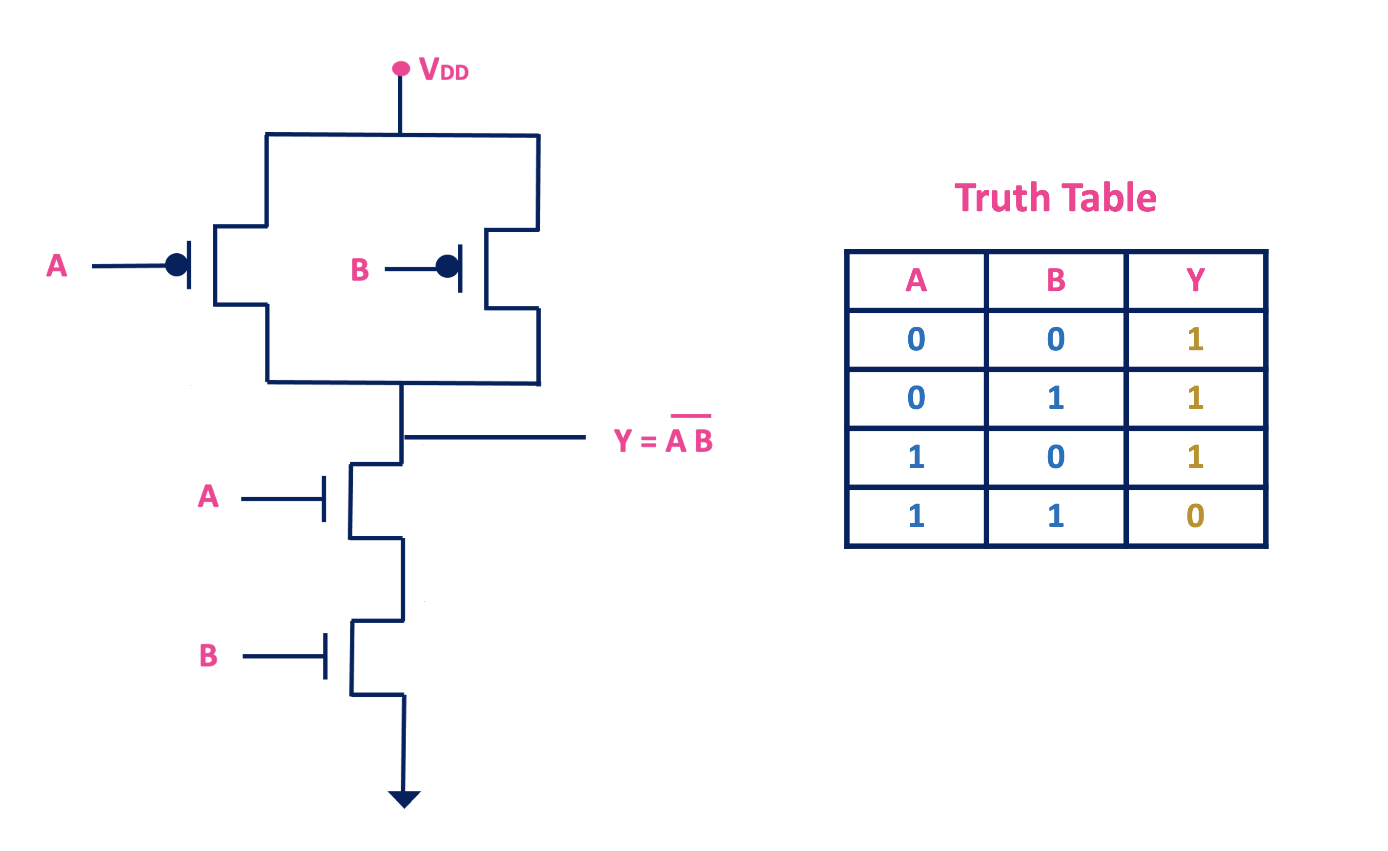
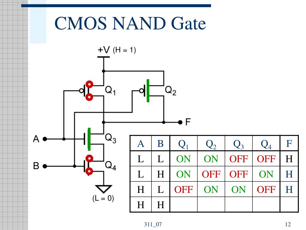
Cmos Logic Gates Explained All About Electronics Fig. 3.3 shows cmos nand gate circuit diagram 2 input nand gate. it consists of two p channel mosfets, q 1 and q 2, connected in parallel and two n channel mosfets, q 3 and q 4 connected in series. p channel mosfet is on when its gate voltage is negative with respect to its source whereas n channel mosfet is on when its gate voltage is positive. A cmos two input nand gate. with q3 and q4 transistors ”on” and q1 and q2 transistors “off,” the output is a logic 0. this condition happens when both inputs, a and b, are logic 1, confirming the lowest row in the above truth table.

Cmos Nand Gate How Its Made And Truth Tables Youtube A basic cmos structure of any 2 input logic gate can be drawn as follows: 2 input nand gate. truth table. circuit. the above drawn circuit is a 2 input cmos nand gate. now let’s understand how this circuit will behave like a nand gate. the circuit output should follow the same pattern as in the truth table for different input combinations. Cmos gates: many paths to vdd and gnd. multiple values for vm, vil, vih, etc. different delays for each input combination. equivalent inverter. represent each gate as an inverter with appropriate device width. include only transistors which are on or switching. calculate vm, delays, etc using inverter equations. Logic nand gate tutorial. the logic nand gate is a combination of a digital logic and gate and a not gate connected together in series. the nand (not – and) gate has an output that is normally at logic level “1” and only goes “low” to logic level “0” when all of its inputs are at logic level “1”. the logic nand gate is the. In this video i show how the basic nand gate is made using complementary mosfet transistors. i introduce truth tables as a method of showing logic states.

Cmos Nand Gate Truth Table Logic nand gate tutorial. the logic nand gate is a combination of a digital logic and gate and a not gate connected together in series. the nand (not – and) gate has an output that is normally at logic level “1” and only goes “low” to logic level “0” when all of its inputs are at logic level “1”. the logic nand gate is the. In this video i show how the basic nand gate is made using complementary mosfet transistors. i introduce truth tables as a method of showing logic states. For a cmos gate operating at 15 volts of power supply voltage (v dd), an input signal must be close to 15 volts in order to be considered “high” (1). the voltage threshold for a “low” (0) signal remains the same: near 0 volts. disadvantages of cmos. one decided disadvantage of cmos is slow speed, as compared to ttl. Definitions. schematic: a drawing of interconnected gates. net: wires at the same voltage (electrically connected) netlist: a list of all the devices and connections in a schematic. fan in: the # of inputs to a gate. fan out: the # of loads the gate drives. 4.

Nand Gate Truth Table For a cmos gate operating at 15 volts of power supply voltage (v dd), an input signal must be close to 15 volts in order to be considered “high” (1). the voltage threshold for a “low” (0) signal remains the same: near 0 volts. disadvantages of cmos. one decided disadvantage of cmos is slow speed, as compared to ttl. Definitions. schematic: a drawing of interconnected gates. net: wires at the same voltage (electrically connected) netlist: a list of all the devices and connections in a schematic. fan in: the # of inputs to a gate. fan out: the # of loads the gate drives. 4.

Comments are closed.