Cmos Circuit Diagram Logic Gates

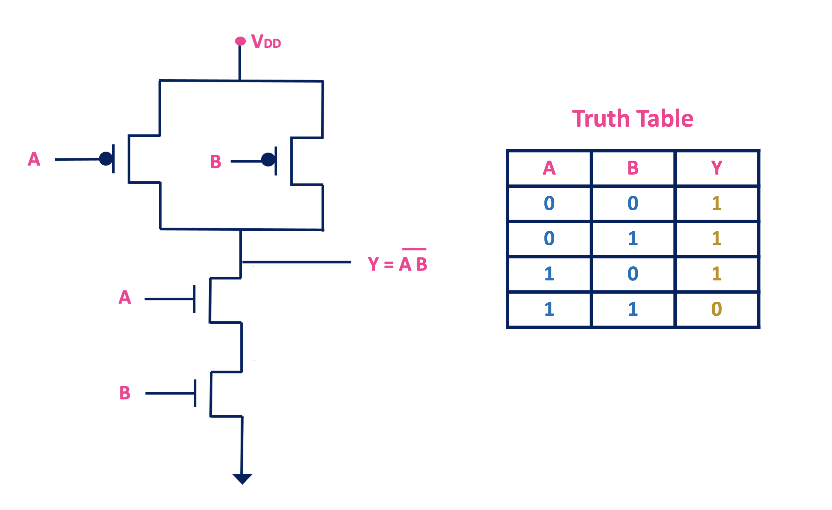
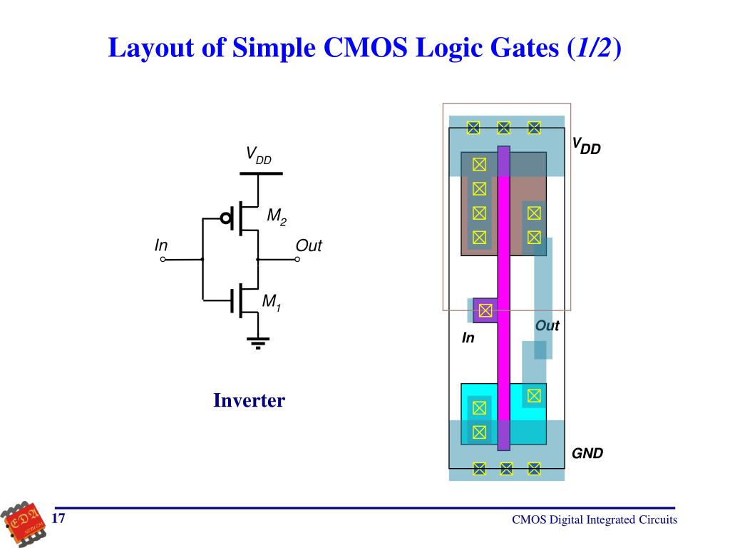
Cmos Logic Gates Explained All About Electronics The logic gates are the basic building blocks of all digital circuits and computers. these logic gates are implemented using transistors called mosfets. a mosfet transistor is a voltage controlled switch. the mosfet acts as a switch and turns on or off depending on whether the voltage on it is either high or low. Basic cmos logic gates. october 27, 2021 by lorenzo mari. learn about gates built with the cmos digital logic family. logic gates that are the basic building block of digital systems are created by combining a number of n and p channel transistors. the most fundamental connections are the not gate, the two input nand gate, and the two input.

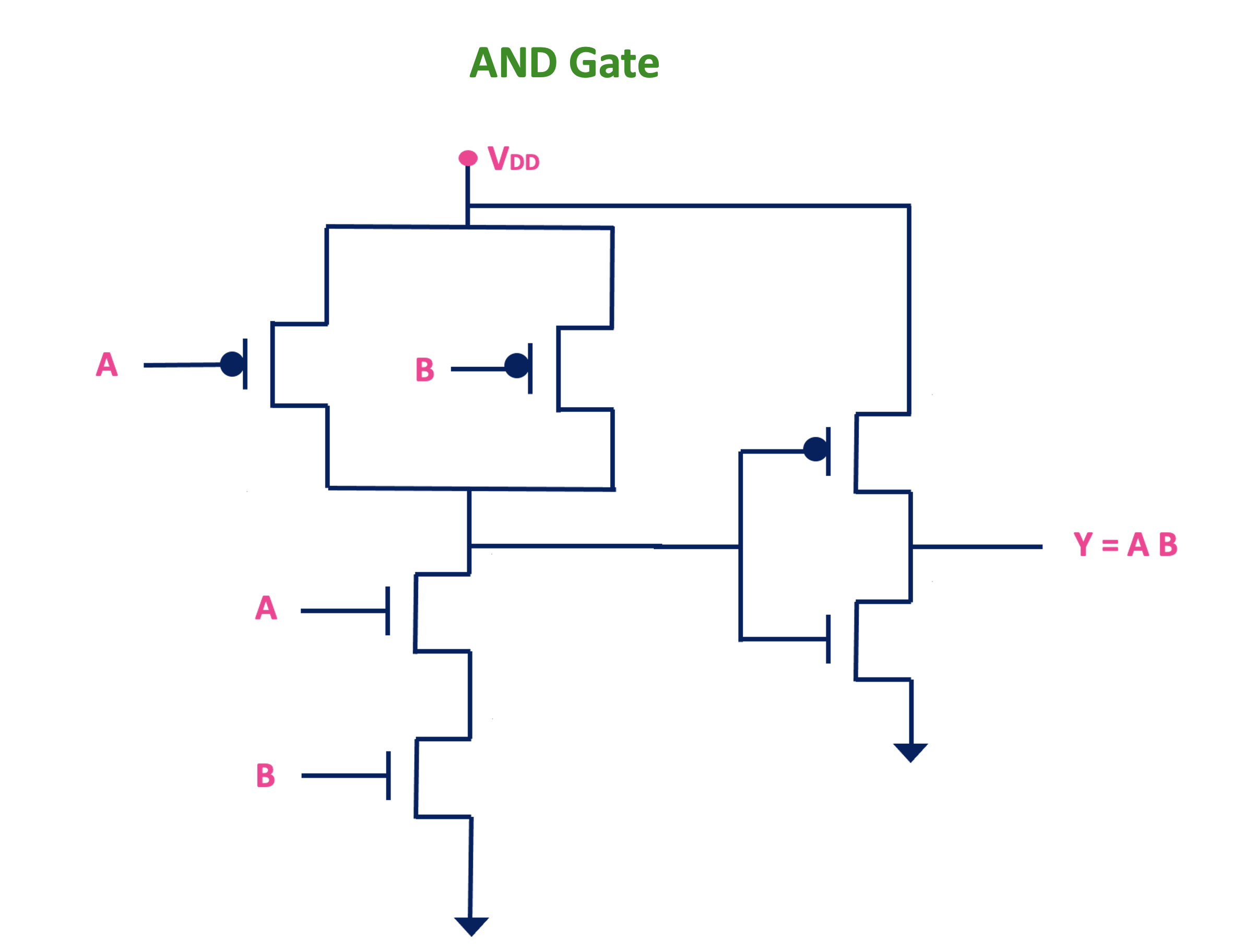
Cmos Logic Gates Explained All About Electronics Cmos circuit behaviors for all logic inputs. the following sequence of illustrations shows the behavior of this nand gate for all four possibilities of input logic levels (00, 01, 10, and 11): cmos and gate. as with the ttl nand gate, the cmos nand gate circuit may be used as the starting point for the creation of an and gate. By controlling the gate to source voltage, pmos and nmos transistor can be used as a switch. and they can be used to design a logic gate. cmos logic uses both nmos and pmos transistors. the pmos transistors are used as pull up network and nmos transistors are used as pull down network. 11 14 2004 example cmos logic gate synthesis.doc 1 6 jim stiles the univ. of kansas dept. of eecs example: cmos logic gate synthesis problem: design a cmos digital circuit that realizes the boolean function: y= ab ac solution: follow the steps of the design synthesis handout! step1: design the pdn first, we must rewrite the boolean function as:. Static cmos circuits §n and p channel networks implement logic functions –each network connected between output and vdd or vss 9 11 18 series network: "and" function parallel network: "or" function page 4.

Cmos Logic Gates Explained All About Electronics 11 14 2004 example cmos logic gate synthesis.doc 1 6 jim stiles the univ. of kansas dept. of eecs example: cmos logic gate synthesis problem: design a cmos digital circuit that realizes the boolean function: y= ab ac solution: follow the steps of the design synthesis handout! step1: design the pdn first, we must rewrite the boolean function as:. Static cmos circuits §n and p channel networks implement logic functions –each network connected between output and vdd or vss 9 11 18 series network: "and" function parallel network: "or" function page 4. Cmos gates: many paths to vdd and gnd. multiple values for vm, vil, vih, etc. different delays for each input combination. equivalent inverter. represent each gate as an inverter with appropriate device width. include only transistors which are on or switching. calculate vm, delays, etc using inverter equations. Basic cmos fabrication steps. growing silicon dioxide to serve as an insulator between layers deposited on the surface of the silicon wafer. doping the silicon substrate with acceptor and donor atoms to create p and n type diffusions that form isolating pn junctions and one plate of the mos capacitor.

Cmos Circuit Diagram Logic Gates Cmos gates: many paths to vdd and gnd. multiple values for vm, vil, vih, etc. different delays for each input combination. equivalent inverter. represent each gate as an inverter with appropriate device width. include only transistors which are on or switching. calculate vm, delays, etc using inverter equations. Basic cmos fabrication steps. growing silicon dioxide to serve as an insulator between layers deposited on the surface of the silicon wafer. doping the silicon substrate with acceptor and donor atoms to create p and n type diffusions that form isolating pn junctions and one plate of the mos capacitor.

Cmos Circuit Diagram Logic Gates

Comments are closed.