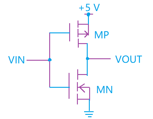
Cmos And The Cmos Inverter Lecture 61

Cmos And The Cmos Inverter Lecture 61 Youtube Cmos, or complementary metal oxide semiconductor, is introduced and the cmos inverter is explained by following the voltage. the inverter is introduced as a. Is the difference between the lowest acceptable ‘1’ and the highest possible ‘1’. nm. = v oh – v ih. t. phl is the propagation delay from the 50% point of the input to the output when the output goes from high to low. t. plh is the propagation delay from the 50% point of the input to the output when the output goes from low to high.

Cmos Inverter Schematic Diagram The cmos inverter is crucial in electronics, employed in memory chips and microprocessors among others. it generates complementary outputs whenever there are input signals through it. these inverters allow flexibility among circuit designers because they can be classified into many categories depending on their abilities and arrangements. Review: dynamic power. each charge discharge cycle dissipates total energy e = c v 2 vdd l dd. to compute power, account for switching the circuit at frequency f. typically, output does not switch every cycle, so we scale the power by the probability of a transition α. 3. cmos inverter: propagation delay. inverter propagation delay: time delay between input and output signals; key figure of merit of logic speed. typical propagation delays: < 1 ns. complex logic system has 20 50 propagation delays per clock cycle. estimation of tp: use square wave at input. vin. Cmos . transfer characteristic gate delay expressions power and speed power product • velocity saturation. general comments impact on mosfet and inverter characteristics. clif fonstad, 11 3 09 lecture 15 slide 1.

Comments are closed.