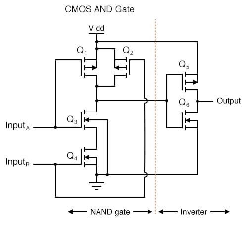
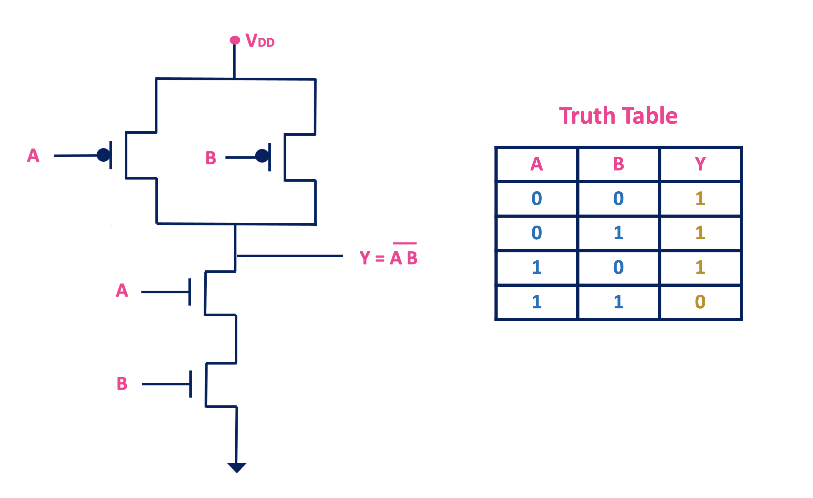
Cmos And Gate Schematic Circuit Diagram

Cmos And Gate Circuit Diagram Enter the Insulated Gate FET (IGFET) which is the basis for most of the transistor devices found on large scale integrated chips today Looking at the diagram, the MOSFETs all show a distinct Basic circuit designs using CMOS transistors; Proper layout structures; Methods for optimizing the area, speed, and power of circuits; Use of CAD tools for both schematic and layout of complex CMOS

And Gate Circuit Diagram Using Cmos Vrogue Co CMOS And TTL part or a 5V tolerant gate in your design, here are a few of the many alternatives A simple resistive downshifter The simplest possible step-down circuit is a resistive In a modern CMOS VLSI chip, the most important function components are CMOS static gates In gate array circuits Static logic gates are the most widely used CMOS circuit because of their The purpose of schematic design is to translate the project program into physical drawings of space In schematic design, the project team determines the areas, physical requirements and relationships When planning how a circuit will function, these headings are then used to plan what the input, process and output could be Producing a schematic drawing on a computer is far neater than drawing

Comments are closed.