Autocad Tutorial Isometric Drawing In Autocad How To Draw Piping

How To Draw Isometric Pipe Drawings In Autocad Gautier Camonect Design hubthis video will show you haw to make autocad piping isometrics step wise. so you will able to make piping iso in easy way.you can download piping i. Isometric drawing plays a vital role in piping design industries, so in this tutorial we had tried to show the details procedure so that you could be able t.

Isometric Drafting In Autocad Tutorial And Videos Fortunately, most modern piping programs—such as the plant 3d toolset—automatically generate an isometric drawing based on the 3d model. the output is typically outstanding, but there are times the designer might need to make edits to the isometric drawing, so most “pipers” are fluent at using the isodraft features in autocad as well. Join us in this comprehensive autocad tutorial where we explore the art of creating accurate plumbing isometric drawings. plumbing isometrics are crucial for. Here is a step by step process of a typical pipe drawing: 1. determine pipe type, material, and size: identify the type of pipe needed for your application, such as copper piping or pvc. 2. create an isometric drawing: start by sketching an isometric drawing of the pipe fitting. Creating an iso pipe drawing. here is an overview of the steps we need to take when creating iso pipe drawings: draw the piping components: select the appropriate pipes, fittings, valves, and other components in the mech q dialog box. common tools include straight pipe elbows and tees for example. activate the isometric grid: within the main.

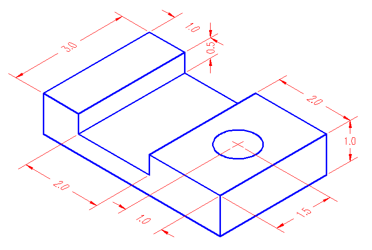
How To Draw Piping Isometric Drawing In Autocad Design Talk Here is a step by step process of a typical pipe drawing: 1. determine pipe type, material, and size: identify the type of pipe needed for your application, such as copper piping or pvc. 2. create an isometric drawing: start by sketching an isometric drawing of the pipe fitting. Creating an iso pipe drawing. here is an overview of the steps we need to take when creating iso pipe drawings: draw the piping components: select the appropriate pipes, fittings, valves, and other components in the mech q dialog box. common tools include straight pipe elbows and tees for example. activate the isometric grid: within the main. A piping isometric drawing is a technical drawing that depicts a pipe spool or a complete pipeline using an isometric representation. the drawing axes of the isometrics intersect at an angle of 60°. although the pipeline is accurately dimensioned, it is deliberately not drawn to scale and therefore does not correspond exactly to a real. Making isometric dimensions. make aligned dimensions a, b and c on the geometry as shown in drawing a above using dimaligned command. now type dimedit on the command line and press enter, select oblique from the command line as shown in the image below. now click on dimension marked a from drawing shown above and press enter.

How To Draw Piping Isometrics In Autocad Autocad Tutorial Youtub A piping isometric drawing is a technical drawing that depicts a pipe spool or a complete pipeline using an isometric representation. the drawing axes of the isometrics intersect at an angle of 60°. although the pipeline is accurately dimensioned, it is deliberately not drawn to scale and therefore does not correspond exactly to a real. Making isometric dimensions. make aligned dimensions a, b and c on the geometry as shown in drawing a above using dimaligned command. now type dimedit on the command line and press enter, select oblique from the command line as shown in the image below. now click on dimension marked a from drawing shown above and press enter.

Comments are closed.