And Gate Using Nand Gate Diagram

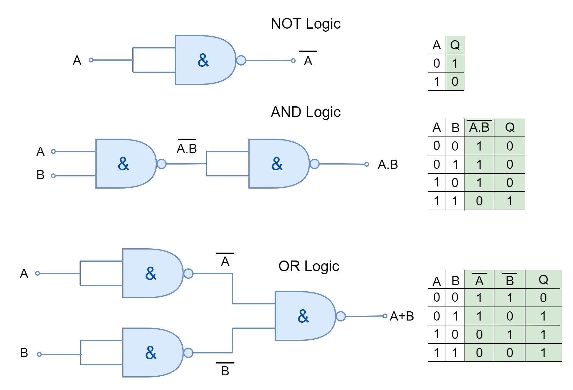
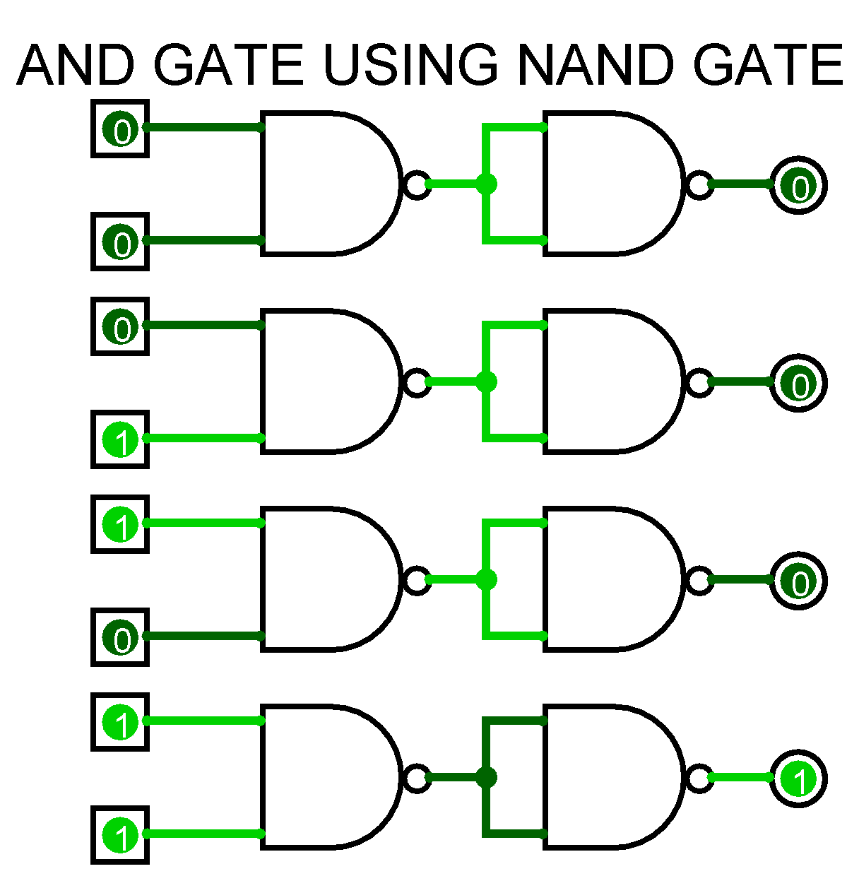
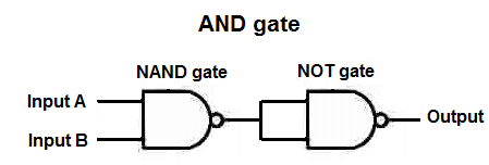
And Gate Using Nand Gate Diagram An and gate can be constructed from nand gates by arranging them in a specific configuration. initially, the two inputs a and b get fed into the first nand gate. from here we get the output of the first gate, which is denoted by “y”, this is fed into the second nand gate, on the same line. at this stage, the output “y” generated by the. The implementation of an and gate using nand gate is shown in figure 3. from this circuit diagram, it is clear that the implementation of the and gate from nand gate is quite simple, as we just require two nand gates. where, the first nand gate produce a complement binary product of inputs a and b, while the second nand gate again complement.

And Gate Using Nand Gate Diagram There are two types of and gates, based on the number of inputs. 2 input and gate. it takes 2 inputs and the truth table will have 22 = 4 possible combinations. the truth table of 2 input and gate is as follows: x=a⋅b. 3 input and gate. it has three inputs and only one output. Circuit diagram of and gate using nand gate: the circuit diagram of the and gate using the nand gate is shown in the following figure. in this circuit, the first nand gate takes two inputs, i.e. a and b, and produces an output as per nand gate operation. after that, the second nand gate acts as an inverter and produces a complemented output. The nand based derivation of the not gate is shown in figure 1. also, it is important to note that the inputs of the nand gates are connected together; the same input. in figure 2 & 3, the nand based configuration was derived, the two possible inputs, zero and one, were tested, and the results were observed. This means it contains 4 nand gates inside of it. to build an and gate from a nand gate, we simply need to use 2 of the 4 gates that a 4011 nand chip offers. conceptually, the and gate is built from nand gates through the following diagram. 2 inputs are fed into the first nand gate. the output of this nand gate is fed into a second nand gate.

To Study And Verify The Truth Table Of Logic Gates вђ Ahirlabs The nand based derivation of the not gate is shown in figure 1. also, it is important to note that the inputs of the nand gates are connected together; the same input. in figure 2 & 3, the nand based configuration was derived, the two possible inputs, zero and one, were tested, and the results were observed. This means it contains 4 nand gates inside of it. to build an and gate from a nand gate, we simply need to use 2 of the 4 gates that a 4011 nand chip offers. conceptually, the and gate is built from nand gates through the following diagram. 2 inputs are fed into the first nand gate. the output of this nand gate is fed into a second nand gate. Or gate truth table is shown below –. 4. nand gate: the nand gate is just a combination of the expression not gate as well as and gate. hence the nand gate is made up of and gate which is followed by an inverter. the working of these gate is like that we get binary 1 at the output of the gate if and only is both the input is at the binary low. And gate 3 circuit diagram. the circuit diagram for and gate 3 is shown above. if you plan to build the circuit this allows all the connection locations to be clearly shown. all the resistor values are set to 2k. this makes it so the led is the proper brightness. and gate built with nand gates. and gate 4 is built using 2 nand gates. each nand.

How To Build An And Gate From A Nand Gate Or gate truth table is shown below –. 4. nand gate: the nand gate is just a combination of the expression not gate as well as and gate. hence the nand gate is made up of and gate which is followed by an inverter. the working of these gate is like that we get binary 1 at the output of the gate if and only is both the input is at the binary low. And gate 3 circuit diagram. the circuit diagram for and gate 3 is shown above. if you plan to build the circuit this allows all the connection locations to be clearly shown. all the resistor values are set to 2k. this makes it so the led is the proper brightness. and gate built with nand gates. and gate 4 is built using 2 nand gates. each nand.

Comments are closed.