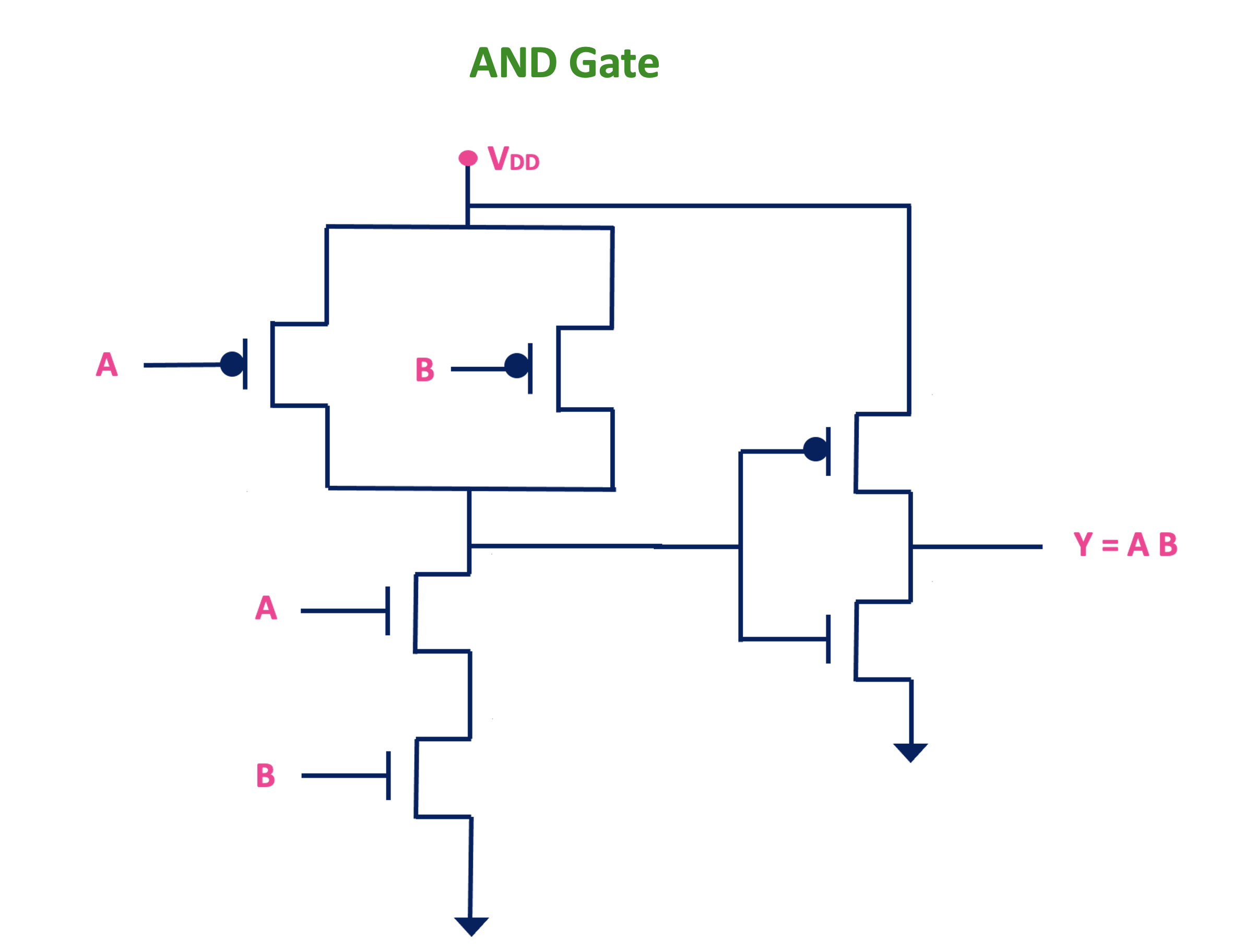
And Gate Cmos Example

Cmos And Gate Circuit Diagram 2 input and gate. it takes 2 inputs and the truth table will have 22 = 4 possible combinations. the truth table of 2 input and gate is as follows: x=a⋅b. 3 input and gate. it has three inputs and only one output. there are 23 = 8 combinations of input and output. x=a⋅b⋅c. In this video i will discuss how to design an and gate signal.

And Gate Cmos Example Youtube When the two are used together to realize the logic gates, they are called cmos (complementary mos). the reason they are called complementary is that nmos and pmos work in a complementary fashion. when the nmos switch turns on, the pmos gets off, and vice versa. cmos inverter: the cmos inverter is shown below. Logic and gate tutorial. the logic and gate is a type of digital logic circuit whose output goes high to a logic level 1 only when all of its inputs are high. the output state of a digital logic and gate only returns “low” again when any of its inputs are at a logic level “0”. in other words for a logic and gate, any low input will give. 3 cmos 3.1 annotated slides worked example: cmos logic gates. transcript. download video; assignment turned in programming assignments with examples. The and gate is a basic digital logic gate that implements logical conjunction (∧) from mathematical logic – and gate behaves according to the truth table. a high output (1) results only if all the inputs to the and gate are high (1). if not all of the inputs to the and gate are high, a low output results. the function can be extended to.

Cmos Logic Gates Explained All About Electronics 3 cmos 3.1 annotated slides worked example: cmos logic gates. transcript. download video; assignment turned in programming assignments with examples. The and gate is a basic digital logic gate that implements logical conjunction (∧) from mathematical logic – and gate behaves according to the truth table. a high output (1) results only if all the inputs to the and gate are high (1). if not all of the inputs to the and gate are high, a low output results. the function can be extended to. And gate circuit diagram: essential for understanding how and gates can be constructed using diodes or transistors to manipulate electrical signals. ic implementation: and gates are implemented in integrated circuits like the 7408 for ttl and 4081 for cmos, each offering multiple gates in a single package. Example of dual rail complex cmos gate 9 11 18 f = g = vdd g f x x y y x x z z page 14. vlsi 1 class notes signal strength §strengthof signal –how close it.

Comments are closed.