Ac Unit Fan Relay Wiring Diagram

Ac Unit Fan Relay Wiring Diagram Again, ensure a secure connection to prevent any loose wires. if you are using a fan center relay, you will need to connect the high voltage wires as well. locate the terminals labeled “line” and “load” on the relay strip. connect the incoming power wires to the “line” terminals, typically labeled as “l1” and “l2.”. In this hvac training video, i show how the fan switching relay works and how to troubleshoot the coil and switching terminal contacts. i take the relay apar.

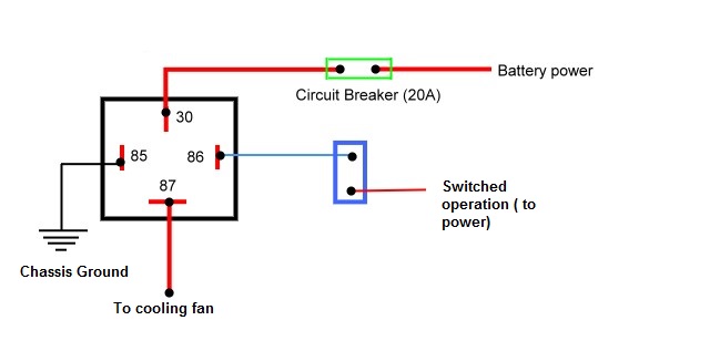
Fan Relay Wiring Diagram Hvac The wiring diagram shows the connections between the power supply, relays, and various components in the air conditioner. it typically includes the input voltage, control signal, and output voltage for each relay. each component is labeled with a specific symbol, making it easy to identify and locate the different elements of the system. About press copyright contact us creators advertise developers terms privacy policy & safety how works test new features nfl sunday ticket press copyright. Step 3: connect the wires to the relay terminals. connect the wire from the control signal (thermostat or control board) to the coil terminal of the relay. this wire will send the control signal to the relay when a temperature change is detected, activating or deactivating the hvac system. First, turn off power to the system for safety. locate the relay in your hvac unit; it’s usually found near the blower motor. remove the relay from its socket and set your multimeter to continuity mode. place one probe on the coil terminal and another on the common terminal.

Comments are closed.