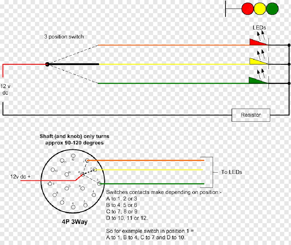
3 Position Rotary Switch Wiring Diagram

3 Position Rotary Switch Wiring Diagram Understanding the wiring process of a 3 position selector switch is crucial to ensure the proper functioning and safety of the electrical system. the switch typically consists of three positions: “off,” “on,” and “on with a different circuit.”. each position has a specific purpose and is wired accordingly to meet the desired outcome. Basic components of rotary changeover switch wiring diagram. a rotary changeover switch wiring diagram includes: 1. rotary switch. this switch is indicated by an arrow in a circle around the central component. it connects a number of terminals in different areas. 2.

3 Position Rotary Switch Wiring Diagram Step 4: wire the load or output devices. next, determine the load or output devices that you want to control with the selector switch. these can be motors, lights, or any other electrical devices. connect the wires from the load devices to the remaining terminals on the selector switch. Ac rotary switches are not ignition protected and may ignite such vapors. using the template provided, drill the mounting surface where the switch is to be mounted. the mounting surface maximum thickness is 0.157” (4.00mm). do not yet fasten the switch to the mounting surface. 3. install source 1, source 2, source 3, and output wires. When wiring a 4 pole 3 position rotary switch, it is important to understand the terminal markings and connections. the switch typically has four terminals labeled a, b, c, and d. the three positions are usually labeled 1, 2, and 3. the wiring diagram will show how each terminal is connected in each position. The third position is usually in the middle, often called the “momentary” position, which means that it is only active when the lever is held or pressed in that position. rotary switch: a rotary switch has a circular body with multiple positions that can be selected by turning a knob or lever. in a three position rotary switch, the knob can.

3 Way Rotary Switch Wiring Diagram When wiring a 4 pole 3 position rotary switch, it is important to understand the terminal markings and connections. the switch typically has four terminals labeled a, b, c, and d. the three positions are usually labeled 1, 2, and 3. the wiring diagram will show how each terminal is connected in each position. The third position is usually in the middle, often called the “momentary” position, which means that it is only active when the lever is held or pressed in that position. rotary switch: a rotary switch has a circular body with multiple positions that can be selected by turning a knob or lever. in a three position rotary switch, the knob can. A 3 position selector switch is a device that allows you to choose between three different options or positions. it is commonly used in electrical circuits and control systems to select different functions or modes of operation. the switch consists of several components that work together to make it function properly. 1. A 3 position selector switch is a type of electrical switch that allows the user to choose between three different positions or settings. it is commonly used in electrical circuits and equipment to control various functions or operations. the switch typically has three terminals or contacts, which are connected to different components or.

4 Pole 3 Position Rotary Switch Wiring Diagram Wiring Diagram A 3 position selector switch is a device that allows you to choose between three different options or positions. it is commonly used in electrical circuits and control systems to select different functions or modes of operation. the switch consists of several components that work together to make it function properly. 1. A 3 position selector switch is a type of electrical switch that allows the user to choose between three different positions or settings. it is commonly used in electrical circuits and equipment to control various functions or operations. the switch typically has three terminals or contacts, which are connected to different components or.

Comments are closed.